Understanding Heliostats
ARTIST is a digital twin for concentrating solar tower power plants. One of the most important components of these
plants are the heliostats, i.e., mirrors that reflect sunlight onto the receiver. Heliostats are not ideal flat
mirrors; they are complex mechanical systems that must be modeled accurately. In ARTIST, heliostats are represented
using three key components: a surface, a kinematics model, and actuators. This page provides a brief overview of
how heliostats are modeled in ARTIST and describes the specific models currently supported.
Surfaces
The surface is the crucial optical component of a heliostat, as it reflects sunlight onto the receiver. This makes
accurately modeling the surface essential. In ARTIST, a heliostat surface is represented by multiple facets, which
can be canted at an angle to improve sunlight concentration.
Most commonly, heliostats in ARTIST have four facets, as illustrated in the figure below:
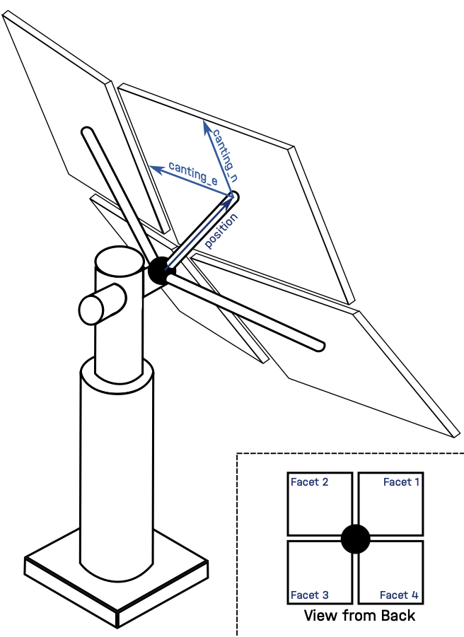
As you can see, each facet has a position relative to a reference point at the heliostat’s center and canting
direction vectors (canting_e, canting_n) that define its orientation.
Kinematics
The heliostat’s kinematics model describes the motion of its mechanical system and determines the final orientation of the heliostat surface for given input parameters, e.g., actuator positions. Actuators are the motor-driven joints that convert control inputs into mechanical motion, allowing the heliostat surface to be oriented toward the receiver. Once the orientation has been computed, the kinematics model calculates the aligned surface points and normals used in the ray tracing. The choice of kinematics model depends on the heliostat design, including the number and type of actuators and the available information about the mechanical system.
The abstract class Kinematics provides methods for aligning the heliostat surface. These methods first compute the
desired heliostat orientation from the input parameters and then applies the corresponding transformation to the surface
geometry. All kinematics implementations derive from this class and override this method.
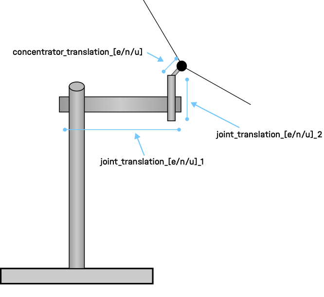
ARTIST currently supports rigid-body kinematics through the RigidBody class. This model represents a heliostat
with two actuators, allowing motion in two directions. The actuators introduce mechanical offsets that are modeled as
translation vectors for three components: joint one, joint two, and the concentrator. The concentrator denotes the
mirror assembly of the heliostat, i.e., the reflective surface and its supporting structure mounted after joint two and
oriented by the actuators. Translation vectors are defined in east, north, and up directions as illustrated below:
In ARTIST, these translations and the possible rotations of each joint are represented by the tensors
translation_deviation_parameters and rotation_deviation_parameters, respectively (see
artist.field.kinematics_rigid_body.RigidBody). This allows multiple heliostats with slightly different
mechanical properties to be modeled efficiently.
Joint one, joint two, and the concentrator all have translations in the east, north, and up directions, resulting in a
nine-dimensional translation_deviation_parameters tensor. The rotation_deviation_parameters describe rotational
deviations of the actuator joints: joint one has deviations in the north and up directions, and joint two in the east
and north direction. This results in a four-dimensional rotation parameter tensor for the rigid-body kinematics model.
Actuators
Heliostat actuators are the motors responsible for adjusting the heliostat surface orientation so that sunlight is
directed toward a specified aim point. Actuators are described by a set of actuator parameters, which may include
information about motor turning direction, step size, and geometric offsets. During initialization, actuator parameters
are separated into non_optimizable_parameters and optimizable_parameters. The abstract class Actuators
defines two core methods: one for mapping motor steps to angles and another for mapping angles to motor steps. All
actuator implementations derive from this class and override these methods.
ARTIST currently supports two actuator types:
LinearActuatorsIdealActuators
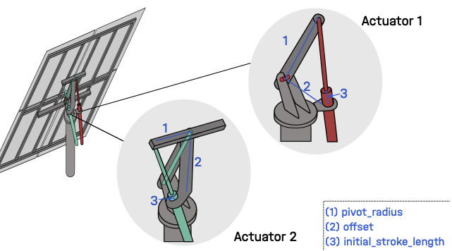
The LinearActuators model is based on the actuator used in the Jülich power plant and includes the parameters
illustrated in the figure below:
Parameter Name |
Description |
|---|---|
|
The type of actuator |
|
A boolean indicating if the movement direction is clockwise |
|
Minimum allowed motor position |
|
Maximum allowed motor position |
|
Number of motor increments per full stroke |
|
Physical offset from the actuator axis to the pivot, (2) in the figure above |
|
Distance from the pivot center to the actuator anchor, (1) in the figure above |
Parameter Name |
Description |
|---|---|
|
Initial angular position of the actuator |
|
Initial extension length of the actuator, (3) in the image above |
In ARTIST, the linear actuator model is physics-informed to prevent invalid values and numerical instabilities
during forward and backward passes. The parameters increment, initial_stroke_length, offset, and
pivot_radius are constrained to be strictly positive using the softplus function, ensuring physically meaningful
values throughout the optimizations.
Additionally, both methods use the law of cosines to convert between motor steps and actuator steps. The stroke length, offset, and pivot radius form a triangle that determines the actuator’s distance from the rotational center of the joint. For the law of cosines to be applicable, the triangle’s sides (offset and pivot radius) must satisfy the triangle inequality:
This constraint ensures that a valid triangle can always be formed. The resulting physics-informed formulation allows the linear actuator to model real actuator behavior accurately and efficiently.
The IdealActuators model has no optimizable parameters. The non-optimizable parameters only include type,
clockwise_axis_movement, min_motor_pos, and max_motor_pos.
Heliostat Blocking
ARTIST supports heliostat blocking, which models the obstruction of reflected rays by other heliostats in the
field. Blocking occurs when a ray reflected from one heliostat toward the receiver intersects another heliostat before
reaching the target. Blocking is therefore a heliostat-field effect that depends on the relative positions and
orientations of neighboring heliostats.
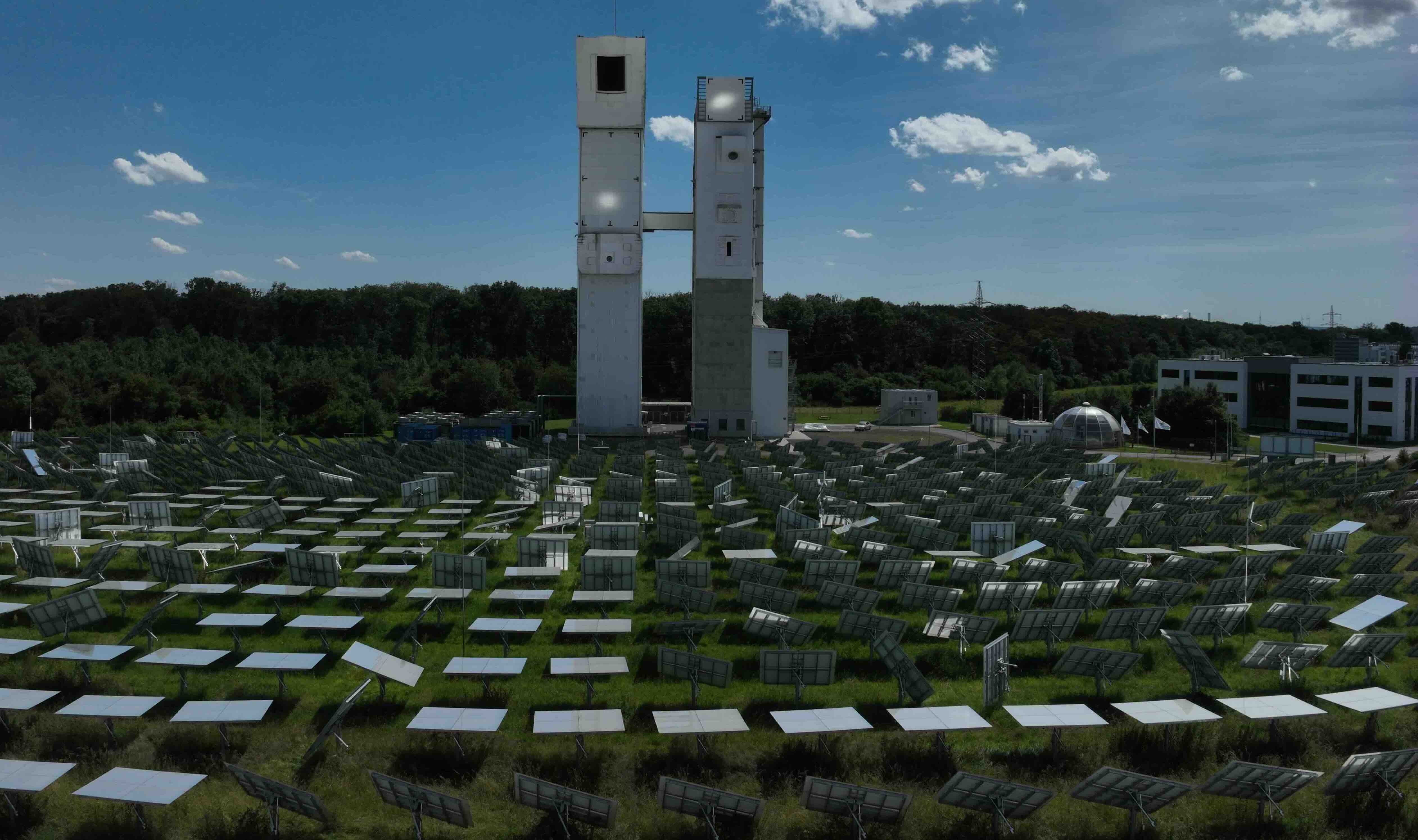
Heliostat blocking in the Jülich heliostat field. Bright spots on the backs of several heliostats reveal where reflected rays from neighboring heliostats are intercepted before reaching the receiver. Credit: DLR (CC BY-NC-ND 3.0)
Blocking is distinct from shading. By definition, shading occurs when incoming sunlight is obstructed before reaching a
heliostat, i.e., between the light source and the reflecting surface. Blocking, in contrast, occurs after reflection,
between the heliostat and the receiver. Currently, only blocking is implemented in ARTIST.
Blocking is computed using ray–geometry intersection tests accelerated by a linear bounding volume hierarchy (LBVH). This acceleration structure follows the approach proposed by Karras and enables efficient intersection queries even for heliostat fields containing thousands of mirrors. The use of an LBVH allows blocking to be evaluated with good scalability while maintaining efficient GPU execution.
If a reflected ray intersects another heliostat, the ray is terminated and does not contribute to the predicted flux distribution on the receiver. Since blocking depends on the relative position of heliostats in the field, it is evaluated individually for each heliostat during the ray-tracing process.
This mechanism should not be confused with global ray extinction in the ray tracer. Global ray extinction models
the loss of ray energy due to atmospheric effects such as dust, fog, or sandstorms. In ARTIST, this is represented
by a global ray_extinction_factor that reduces the energy of all rays uniformly along their path. Unlike blocking,
which completely terminates rays due to geometric occlusion, atmospheric extinction only attenuates the ray energy and
is assumed to be spatially uniform across the heliostat field.
Blocking is enabled during motor position optimization, where accurate flux prediction is required. For surface and kinematics reconstruction tasks, blocking is automatically disabled to reduce computational cost and improve optimization stability. This behavior is fixed internally and cannot be modified through user input.